Introduction
Ensuring a reliable and efficient water supply is crucial for homes,
farms, and businesses. Manual water management is time-consuming and
error-prone, often leading to waste or shortages. With modern technology, you
can automate your water system for real-time monitoring, efficiency, and
peace of mind.
Diving Deeper into the Components
Let's take a closer look at each crucial component and its role in your smart water management system:

fig. 1
Cerbo GX: The Intelligent Hub: Think of the Cerbo GX as the brain of your water management system. This versatile device from Victron Energy acts as a central communication hub, seamlessly connecting all other components. It gathers data, executes automation rules, and provides a user-friendly interface for monitoring and control. Whether you're checking levels on its local display or remotely via Victron's VRM (Victron Remote Management) portal, the Cerbo GX puts you in command. It supports various communication protocols, ensuring smooth integration with a wide range of devices.
fig. 2
GX Tank 140: Precision Level Monitoring: The GX Tank 140 is specifically designed for accurate tank level measurement. It acts as an interface between analog sensors, like our submersible level sensor, and the digital world of the Cerbo GX. By converting the sensor's analog signal into a digital reading, the GX Tank 140 provides precise and reliable water level data, crucial for effective automation and monitoring. It can often handle multiple tank sensors, making it scalable for more complex setups.Relays and Contactors: The Power Switches: Relays and contactors act as electrically controlled switches that govern the operation of your water pump and potentially the solenoid valve. Relays are typically used for lower power applications, while contactors are necessary for handling the higher current demands of most water pumps. The Cerbo GX sends signals to these switches based on the automation rules you define, turning the pump on or off.

fig. 3
Submersible Level Sensor (4-20mA): The Accurate Eye in the Tank: This sensor is the workhorse for measuring the water level within your tank. Submerged at the bottom, it emits a 4-20mA current signal that is directly proportional to the depth of the water. This industry-standard signal is highly reliable and less susceptible to electrical noise compared to voltage-based sensors, ensuring accurate readings even in challenging environments. The 4mA reading typically corresponds to an empty tank, while 20mA indicates a full tank.Water Pump: The Force Behind the Flow: The water pump is responsible for moving water into or out of your tank, depending on your system's design and requirements. Selecting the right pump with appropriate flow rate and pressure specifications is crucial for efficient operation. Your automation system will control this pump, ensuring it operates only when needed, saving energy and extending its lifespan.

fig. 4
Solenoid Valve: The Automated Gatekeeper: The solenoid valve acts as an electrically controlled gate for your water flow. When energized, it opens to allow water to pass; when de-energized, it closes to stop the flow. Integrating a solenoid valve into your smart system provides an additional layer of control, allowing you to precisely manage when and how water enters your tank, often used in conjunction with the pump to prevent overfilling or to manage filling schedules.

This component allows you to step down a higher voltage (like 240/120V) to supply the lower voltage requirements (e.g., 12V or 24V DC) for components like the Cerbo GX, GX Tank 140 & solenoid valve, or to precisely regulate power for other parts of your system. Its adjustable output provides flexibility in meeting diverse power demands, though its specific application depends on the overall system architecture.
Why Go Smart? Key Benefits
- Complete Automation: No more manual pump or valve operation
- Water Conservation: Prevents overfilling and running dry
- Real-Time Visibility: Monitor tank levels and pump status locally or remotely
- Early Problem Detection: Get alerts for low/high levels or malfunctions
- Scalability: Easily expand
to more tanks or integrate with solar/off-grid systems
Step 1: Meticulous Planning for Seamless Setup
Before you start wiring, plan carefully:
- Assess Your
Tank:
- Precise Dimensions: Accurately measure the height and, if applicable, the diameter or other relevant dimensions of your water tank. This data is critical for correctly calibrating the GX Tank 140 and ensuring accurate level readings displayed as a percentage or volume.
- Tank Material and Shape: Consider the material and shape of your tank as this might influence sensor placement and potential mounting considerations.
- Inlet and Outlet Locations: Understand the locations of your water inlet and outlet pipes to plan the placement of the pump and solenoid valve effectively.
- Pump Selection and Specifications:
- Flow Rate: Determine the required flow rate (liters or gallons per minute) based on your water demand.
- Head (Pressure): Calculate the total dynamic head (TDH), which includes the vertical distance the water needs to be lifted and any friction losses in the pipes. Choose a pump with sufficient pressure to meet these demands.
- Power Requirements: Note the voltage and current requirements of your pump to select appropriate relays or contactors and ensure adequate power supply.
- Plan Sensor
Placement:
- Optimal Location: The submersible level sensor should be installed at the lowest point of your tank to provide a reading across the entire water level range. Ensure it is positioned away from any obstructions or turbulent water flow that could affect its accuracy.
- Secure Mounting: Plan how you will securely mount the sensor. Some sensors come with weighted bases, while others may require a suspension mechanism. Ensure the wiring is protected from damage and water ingress.
- Map Out Wiring
& Safety:
- Plan Cable Routes: Determine the paths for all electrical cables, ensuring they are protected from physical damage, moisture, and UV exposure.
- Safety First: Always prioritize safety. Plan for proper grounding and consider using appropriate conduit or cable trays.
Tip: If unsure about
electrical work, consult a qualified electrician.
Step 2: Install & Connect Hardware
Follow these steps:
- Careful Installation of the Submersible Level Sensor:
- Gentle Placement: Carefully lower the sensor to the bottom of the tank, ensuring it rests securely. Avoid dropping it, which could damage the sensitive components.
- Secure Connections: Connect the sensor's positive and negative output wires to the designated analog input terminals on the GX Tank 140 module. Use appropriate, waterproof connectors to prevent corrosion and ensure a reliable signal. Refer to the datasheets for both the sensor and the GX Tank 140 for correct wiring diagrams and polarity.
- Establishing Communication: Connecting GX Tank 140 to Cerbo GX:
- Mount the GX Tank 140: Choose a suitable, secure location for the GX Tank 140. It should be close enough to your tank sensors for their wiring, and also within reach of the Cerbo GX for the USB cable. Consider protection from the elements if installed outdoors.
- Connect Tank Sensors to GX Tank 140:
- The GX Tank 140 supports up to four tank level sensors.
- It's compatible with various sensor types, typically 4-20mA current sensors or 0-10V voltage sensors. Ensure your chosen tank sensors are compatible with the GX Tank 140.
- Wire your tank sensors to the appropriate input terminals on the GX Tank 140 using the pluggable terminal blocks provided for easy connection.
- Important Note on Sensor Power:
- Channels 1 and 2 on the GX Tank 140 can often use a fused power source from the Vin connection (external power supply to the GX Tank 140's auxiliary power input) for sensor excitation.
- Channels 3 and 4 often have an integrated 24V power source for sensor excitation, powered via the USB connection from the Cerbo GX. This simplifies wiring as no additional power source is needed for sensors connected to these channels.
- Always refer to the GX Tank 140 manual for specific wiring details for your sensor type and power requirements.
- Connect GX Tank 140 to Cerbo GX via USB:
- Take the USB cable (usually integrated) from the GX Tank 140.
- Plug it into one of the available USB ports on your Cerbo GX. The Cerbo GX typically has multiple USB ports. This connection also provides power to the GX Tank 140.
- Secure Cabling: Ensure the USB cable connection is firm and secure.
- Power Up the Cerbo GX: Ensure your Cerbo GX is powered on.
- Initial Configuration Check in Cerbo GX (via GX Touch or VRM):
- Once connected and the Cerbo GX is powered, the GX Tank 140 should automatically appear as a recognized device in the Cerbo GX's device list.
- Access the Cerbo GX's interface (either via a directly connected GX Touch display, or remotely through the Victron Remote Management (VRM) portal).
- Navigate to the Devices list and confirm that the GX Tank 140 is detected.
- Configuration within Cerbo GX (Detailed in Step 3): This initial check confirms the physical connection. Detailed calibration and tank assignment will be covered in Step 3.
- Wire Control
Elements
- Relay Connections: Connect the control wires through the Cerbo GX's relay terminals to the coil terminals of the separate relays. The relay's normally open (NO) or normally closed (NC) contacts will then be used to control the contactor's coil or directly switch a low-power pump or the solenoid valve.
- Contactor Wiring (for high-power pumps): The relay's output contacts will switch the low-current control circuit of the contactor. The main power wires for your water pump will then be connected through the heavy-duty contacts of the contactor. Ensure proper wiring according to the wiring diagram.
- Solenoid Valve Wiring (if used): Similar to the pump (or potentially directly through a relay if its power requirements are low enough), wire the solenoid valve to be controlled by another relay of the Cerbo GX or through a separate relay.
- Power the Pump
Safely
- Correct Wiring: Connect the water pump to the output terminals of the contactor, ensuring you follow the wiring diagram and all local electrical codes.
- Grounding: Properly ground the pump to protect against electrical faults.
- Overcurrent Protection: Ensure you have appropriate fuses, motor saver, or circuit breakers in place to protect the pump and the electrical system.
- Provide Stable
Power
- Dedicated Supplies: Provide stable power to all components. It's often recommended to have a separate, reliable power source for the Cerbo GX and GX Tank 140 (typically 12V or 24V DC) and another for the higher-voltage pump.
- Isolation: Keep high-voltage wiring (for the pump and contactor) physically separated from low-voltage wiring (for the Cerbo GX, GX Tank 140, and sensors) to prevent interference and ensure safety
The wiring diagram in fig. 6 outlines a smart water management and automation system designed to optimize water delivery and tank levels across multiple storage units. This setup specifically addresses a scenario where a single-phase, 3 horsepower, 240-volt water pump supplies water from various tanks—two 1000-gallon, one 2750-gallon, and one 2850-gallon—to multiple buildings.
Each tank in the system receives its supply from the main utility water line via a solenoid valve. These solenoid valves are controlled by Cerbo GX Relay 2. This relay is configured for manual operation, allowing you to manage the incoming utility water supply to fill the tanks either directly from the Cerbo GX touch screen display or remotely through the VRM portal via a web browser on a computer or mobile device.
The Cerbo GX relay also controls the water pump. Since the Cerbo GX's internal relays are low-power, they are used to switch a separate, higher-power relay. This separate relay's coil terminals are connected to the Cerbo GX relay terminals. This higher-power relay, in turn, controls the coil of a contactor. The main 240V power supply wires for the water pump are routed through the heavy-duty contacts of this contactor. This ingenious setup allows the Cerbo GX to control the pump's circuit.
Ultimately, the system is designed to automatically manage tank levels: whenever a tank reaches a pre-set low level (e.g., nearing empty), it would turn off the water pump to prevent dry running and ensure efficient water distribution.
 |
| fig. 6 |
Warning: Always follow local
electrical codes and safety practices.
Step 3: Configure the Cerbo GX
Set up your system for smart automation:
- Tank Level
Monitoring
This involves two main parts for each tank connected to the GX Tank 140:
- General Tank
Settings: Assigning names, liquid types, sensor types (4-20mA), capacity, and
tank shape.
- Calibration: Teaching the
system what 4mA (empty) and 20mA (full) correspond to in terms of
percentage or volume.
Part 1: Accessing the Cerbo GX Interface
The steps to navigate the menus are largely identical whether you're using the physical touchscreen or the VRM Remote Console.
A. Via GX Touch 50/70 (Physical Touchscreen Display):
- Wake the
screen: If the screen is off, tap it to wake it up.
- Open Remote Console: From the initial screen that appears, navigate to and tap/click on "Remote Console." This will bring up the main Venus OS interface, ready for interaction
B. Via VRM Portal (Remote Console):
- Log in to VRM: Open your web
browser and go to https://vrm.victronenergy.com/. Log in with your Victron VRM
account.
- Select your
installation: Choose the specific Victron installation you want to manage from
your dashboard.
- Open Remote
Console: In the left-hand menu, click on "Remote Console."
This will open a new window or tab displaying your Cerbo GX's interface,
just as if you were looking at the physical touchscreen.
.png)
fig.
Part 2: Configuring GX Tank 140 General Settings
Once you've accessed the Cerbo GX interface (either locally or via VRM), follow these steps:
- Access the
Devices: From the remote console, navigate to "settings."
- Find the GX
Tank 140: In the Devices, scroll down until you find the GX Tank 140 4 inputs.
- Select a Tank
Instance: You'll see "Tank 1,"
"Tank 2," "Tank 3," and "Tank 4."
- Tap/click on
the specific tank input that has a sensor connected (e.g., "Tank
1").
- Configure Tank-Specific Settings (for each connected tank): On the screen for the selected tank (e.g., "Tank 1") scroll down until you find 'setup' then:
- a. Fluid Type:
- Tap/click on "Fluid type."
- Select the
appropriate type from the list:
- Water: For fresh
water.
- Fuel: For fuel
tanks.
- Waste water: For
black/grey water tanks.
- This helps
with proper labeling and icon display.
- b. Sensor
Type:
- Tap/click on "Sensor
type."
- Crucially,
select "Current (4-20mA)." This tells the GX Tank 140 to
interpret the sensor's signal as a 4-20mA current loop.
- c. Capacity:
- Tap/click on "Capacity."
- Enter the total
volume of the tank in gallons (or liters, depending on your system's
unit settings). This is the maximum volume the tank can hold.
- Tap
"OK" or the checkmark to save.
- d. Custom Shape:
- Tap/click on "Custom shape."
- Choose the
shape that best represents your tank:
- Rectangle: For square
or rectangular tanks (most common for simple, linear readings).
- Cylinder
(horizontal): For cylindrical tanks lying on their side.
- Cylinder
(vertical): For cylindrical tanks standing upright.
- Custom: If your
tank has an irregular shape, you'll need to use the "custom"
option, which allows you to define multiple calibration points (e.g.,
25%, 50%, 75% points), not just empty and full. For 4-20mA
empty/full calibration, "Rectangle" is usually sufficient
even if the tank isn't perfectly rectangular, assuming the sensor
provides a linear output. If you need accurate intermediate
readings for a non-linear tank, "Custom" calibration would be
required, involving more points than just 4mA/20mA.
.png)
- a. Device Name:
- Go back to tank input (e.g., "Tank 1") then select 'device'
- Tap/click on "Name."
- Use the on-screen keyboard to enter a descriptive name for your tank (e.g., "Main Water Tank," "Grey Water," "Fuel Tank," "East Building Tank").
- Tap "OK" or the checkmark to save.
.png)
Part 3: Calibrating 4mA (Empty) and 20mA (Full) Readings
This is where you tell the GX Tank 140 what current value corresponds to an empty tank and what current value corresponds to a full tank.
Preparation for Calibration:
- For 4mA (Empty)
Reading: Ideally, your tank should be empty or at its absolute
minimum level. The sensor should be correctly installed and powered.
- For 20mA (Full)
Reading: Ideally, your tank should be full or at its absolute maximum
level.
Calibration Steps (for the selected tank, e.g., "Tank 1"):
- Navigate to the
Tank Calibration Menu:
- From the
individual tank's settings screen (e.g., "Tank 1") select 'setup' scroll down.
- You should see
options for "Sensor value when empty" and "Sensor value when full."
.png)
- Calibrate Empty
(4mA Point):
- Ensure your
tank is at its empty state.
- Tap/click on "Sensor value when empty."
- The system
will display the current mA reading from the sensor.
- Tap/click "Set
as empty." The Cerbo GX will then record this current value as
the 0% (empty) point for your tank.
- Calibrate Full
(20mA Point):
- Now, ensure
your tank is at its full state.
- Tap/click on "Sensor value when full."
- The system
will display the current mA reading from the sensor.
- Tap/click "Set
as full." The Cerbo GX will record this current value as the
100% (full) point for your tank.
Important Notes on Calibration:
- Stability: Ensure the
tank level is stable during calibration.
- Sensor Output: The system
will simply record the mA value it receives. If your sensor itself is
faulty or miscalibrated, the readings will be inaccurate. A true 4-20mA
sensor should output near 4mA when empty and near 20mA when full.
- Non-Linear
Tanks: If you have an irregularly shaped tank and need accurate
intermediate readings (e.g., 25%, 50%, 75%), you should use the "Custom"
tank shape and perform additional calibration points. The 4mA and 20mA
calibration only sets the endpoints (0% and 100%).
Part 4: Verification
- Return to
Device Main Screen: click on 'Levels'
.png)
- Check Readings: Observe the
tank level displayed for your configured tank. As the tank fills or
empties, the percentage and calculated volume should update in real-time.
By following these detailed steps, you should be able to successfully configure and calibrate your GX Tank 140 for accurate 4-20mA sensor readings.
- General Tank
Settings: Assigning names, liquid types, sensor types (4-20mA), capacity, and
tank shape.
- Automation
Rules
.png)
.png)
.png)
.png)
.png)
- This is where you define the brain of your system, telling the Cerbo GX when to activate or deactivate the pump and potentially your utility valve based on your tank levels.
- Assign Outputs for Pump and Valve Control
First, you need to tell the Cerbo GX which relay controls which function.
- Access Relay
Settings:
- Via GX Touch
(Touchscreen): From the main menu, go to Settings > Relay.
- Via VRM Portal
(Remote Console): From the Remote Console, go to Settings > Integration
> Relay.
.png)
- Assign Pump Control Relay:
- For the pump, select its connected relay (such as Relay 1) and set its Function to Tank pump.
.png)
- For the valve (connected to Relay 2, for example), set its Function to Manual if you prefer direct user control
.png)
Set Logic: e.g., Pump ON above 10%, OFF below 5% (add hysteresis)
This is where you define the specific levels that trigger your pump (or automated valve).
1. Select the Controlling Tank:
o After setting a relay's function to 'Tank pump', go back to the main settings screen.
o Tap/click on 'Devices' option
o Scroll down until you see a new option appear: 'Tank pump'
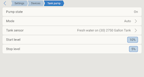
o Tap/click on 'Tank pump' option
o Tap/click on the 'Tank sensor' option and select the specific tank that this relay should monitor to make its decisions (e.g., if the pump supplies from "Main Water Tank" and you want to protect it from running dry, select "Main Water Tank").
2. Configure ON and OFF Percentages:
o Go back to 'Tank pump' option, now that tank sensor is set, new options will appear:
§ Start level
§ Stop level
o Understanding Your Logic ("Pump ON above 10%, OFF below 5%"): This logic is typically used when a pump is supplying water from a source tank and you want to ensure the pump only runs when there's enough water in that source tank to prevent dry-running.
§ Start level:
§ Set this to 10%. This means the relay will close (turn the pump ON) only when the selected tank's level is 10% or higher. This ensures the pump has sufficient water to start drawing.
§ Stop level
§ Set this to 5%. This means the relay will open (turn the pump OFF) when the selected tank's level drops below 5%. This acts as a dry-run protection, shutting off the pump before the tank is completely empty.
o Understanding Hysteresis:
§ Definition: Hysteresis is the difference between the ON and OFF setpoints. In our example, 10% (ON) and 5% (OFF) creates a 5% hysteresis.
§ Purpose: It prevents rapid cycling of the pump (or valve). Without sufficient hysteresis, if the tank level fluctuates around the activation/deactivation points (e.g., between 5% and 10%), the pump could switch on and off repeatedly, causing excessive wear. The 5% buffer ensures that once the pump turns off below 5%, it won't turn back on until the tank level recovers significantly (to 10% or above), even if it briefly bounces above 5%.
3. Alerts & Notifications
A. Accessing Alarm Settings
The process to access the alarm configuration is the same whether you're using the GX Touch 50/70 or the VRM Remote Console.
- Navigate to
Main Dashboard then go to setting.

- Access Alarm
Settings:
- Via GX Touch
(Touchscreen): Tap on "Alarm rules" from the main menu.
- Via VRM Portal
(Remote Console): Click on "Alarm rules"
from the main menu.

B. Setting Up Alerts for Water Management
You can configure several types of alarms to monitor your water system effectively.
1. Tank Level Alarms (Low / High)
These alerts notify you when a specific tank's level drops too low (e.g., running out of water) or rises too high (e.g., risk of overflow).
- Access Tank
Alarms: From the main "Alarm rule" menu, select "Add a new alarm rule."

- From the 'Devices' section select the specific Tank: You'll see a list of your configured tanks (e.g., "Tank 1
(Main Water Tank)", "Tank 2 (Grey Water)"). Tap/click on
the tank you want to set an alarm for.
- Select the 'Parameter' tank capacity

- Tap/click on next
- Configure Low
Level Alarm:

- Tap/click on "Low
level alarm."
- Action:
- Set the percentage at which you want a warning (e.g., 15%).
- Set the clear low alarm above value: When a low-level alarm is active, it will automatically clear after the tank's level (not capacity) rises above this specified percentage. (For example, if your alarm triggers at 10%, you might set the clear value at 12% to ensure the level has recovered sufficiently before the alarm clears.)
- Configure High
Level Alarm:
- Tap/click on "High
level alarm."
- Action:
- Set the upper percentage for a warning (e.g., 90%).
- Set the clear high alarm below value: When a high-level alarm is active, it will automatically clear after the tank's level (Tank capacity) drops below this specified percentage. (For example, if your alarm triggers at 95%, you might set the clear value at 93% to confirm the level has significantly receded from the high point.)
C. Choose Notification Methods (Email, Push, etc.)
Once an alarm condition is met, the Cerbo GX needs to know how to notify you. These settings are primarily managed through the VRM Portal, as VRM is the cloud service that sends the notifications.
- Access VRM
Alarm Notifications:
- Log in to your
VRM Portal at https://vrm.victronenergy.com/.
- Select your
installation.
- In the
left-hand menu, go to Alarms -> Alarm
monitoring.
- Image
Description (VRM Alarm Monitoring): You'll see a list of recent
alarms and, importantly, a section or button for "Alarm
rules" or "Notification settings."
- Configure
Notification Rules:
- Action: Click on "Alarm
rules" or similar (the exact wording might vary slightly over
time).
- You'll see a
list of all possible alarm types (Tank low, Tank high, Relay runtime,
etc.).
- Action: For each
alarm type you've configured on the Cerbo GX, select how you want to be
notified:
- Email: Check the
box next to "Email" to send notifications to the email address
associated with your VRM account.
- Push
Notification: Check the box next to "Push" to send
notifications to your smartphone via the VictronConnect app (ensure your
VictronConnect app is linked to your VRM account and has notifications
enabled).
- SMS: (Less
common, often requires specific setup or third-party services, and may
incur costs).
- Relay: In some
advanced setups, an alarm can trigger a specific relay on the Cerbo GX
(e.g., to activate a local buzzer or light). This would be configured in
the Cerbo GX itself under Settings -> Relay by setting a
relay's function to Alarm relay.
Important Notes:
- Test Your
Alarms: After configuration, simulate an alarm condition (e.g., by
temporarily adjusting a threshold or disconnecting a sensor for a moment)
to ensure you receive notifications as expected.
- Avoid
Over-Alerting: Too many trivial alerts can lead to "alarm fatigue,"
causing you to ignore important ones. Set thresholds meaningfully.
- VRM Account Settings: Ensure your email address in your VRM profile is correct and that you check your spam/junk folder if emails aren't arriving.
- Navigate to
Main Dashboard then go to setting.
-
Step 4: Monitor & Optimize
- Local
Monitoring: View tank levels, pump status, and alerts on Cerbo GX screen
- Remote Access: Use
Victron VRM portal for live/historical data and notifications
- Analyze Data: Review
usage patterns and optimize automation rules
- Troubleshoot: Use
system logs for diagnostics
Troubleshooting & FAQ
Q: My tank level readings are inaccurate. What should I check?
A: Ensure the sensor is installed at the lowest point, wiring is secure, and calibration is correct.
Q: The pump doesn’t turn on/off as expected.
A: Double-check automation rules, relay/contactor wiring, and ensure thresholds are set with hysteresis.
Q: I’m not receiving alerts.
A: Verify alert settings in Cerbo GX/VRM portal and check your notification preferences.
Q: Can I expand the system to more tanks?
A: Yes! The GX Tank 140 supports up to four sensors and the Victron ecosystem is highly scalable.
Summary
A smart water management system using the Victron Cerbo GX and GX Tank 140 brings automation, efficiency, and peace of mind to your water supply—whether at home, on a farm, or in a business. With careful planning, installation, and configuration, you’ll enjoy reliable water delivery, real-time monitoring, and the flexibility to expand as your needs grow.
Take control of your water resources—upgrade to smart automation today!
Setting up alerts is crucial for proactive management. It ensures you're immediately aware of critical situations, allowing you to respond quickly to prevent issues like running out of water, overflowing tanks, or pump malfunctions.
.png)
.png)
.png)


.png)


.png)
3 Comments
This smart water management system sounds like a game-changer! Integrating the Victron Cerbo GX and GX Tank 140 brings advanced control and real-time monitoring to any setup. The ability to set alerts adds a valuable layer of protection and peace of mind. It’s a smart investment for anyone serious about efficient water use.
ReplyDeleteVery informative article. Every part of the article was meaningful. I came to know many more information from the post. Thank you for sharing.
ReplyDeleteI'm so happy to hear you found the article informative and gained valuable insights from the post. Thanks for taking the time to read and share your positive feedback!
DeleteWe'd love to hear from you! Share your questions, thoughts, or feedback on this post. Your input helps us create even better tutorials. What topics would you like us to cover next?